Hey folks, let’s cut to the chase—if you’re in progressive dies, you know the stripper plate isn’t just a flat piece of metal that holds parts in place as the punch descends. I’ve been supplying progressive dies and related components for 12 years, and I’ve seen so many shops skip over stripper plate design only to end up with stripped punches, scrap galore, and machines sitting idle. Today, I’m walking you through how to design a stripper plate that actually works—no fancy jargon, no overcomplicated steps, just the stuff that’s actually saved my clients thousands of bucks. Progressive Dies
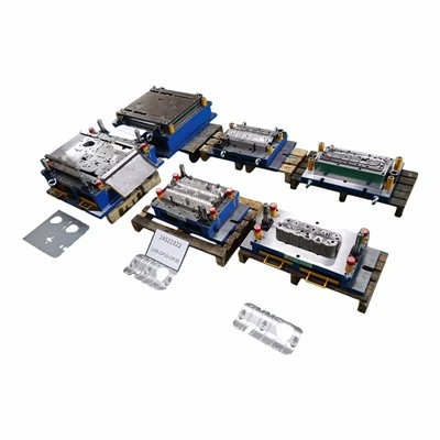
First, let’s get one thing straight: the stripper plate’s main job isn’t just “stripping the part.” It’s also guiding the punch, controlling die clearance, and keeping the strip from shifting mid-cycle. Mess that up, and you’re looking at bent punches, off-size parts, and way too much downtime. I’ve fixed more dies where the stripper was cut too thin or aligned wrong than I can count, so let’s start with the non-negotiables.
First up, material selection. A lot of new guys grab plain steel because it’s cheap, and that’s a rookie mistake. If you’re running 40,000 to 50,000 strokes a week (which is standard for most production runs), you need something that can take the constant friction and punch impact. I swear by tool steels for the majority of stripper plates—specifically D2 or A2. D2’s got great wear resistance, perfect for when you’re stamping hard materials like stainless steel or aluminum that’s been annealed. A2’s a bit tougher for heavier impact loads, so I use that for parts where punches are moving through thicker material, like 1/8” steel. Wait, and if you’re running thin, soft stuff—like 0.01” copper for connectors—you can use a pre-hardened steel like 4140. It’s cheaper, and you don’t need the extra wear resistance when the strip’s super flimsy. Just don’t use mild steel for high-production runs. I had a client who tried that once for a auto body stamping—stripper wore out in 2 weeks, had to shut down the line to replace it. Cost them 8 hours of labor and scrap parts that were already half-made. That’s the kind of newbie move I want you to avoid.
Next, the critical dimension: stripper plate thickness. This isn’t a random number you guess. Too thin, and it’ll flex when the punch hits, throwing off alignment. Too thick, and you’re wasting material, not to mention adding unnecessary weight that strains the die set. The rule I live by is: measure the thickest material you’re stamping, add twice the punch diameter of the largest punch in that station, then add 0.125 inches for clearance for fasteners and the stripper pins. Wait, let’s make that concrete. If I’m stamping 0.06” thick steel, and my biggest punch is 0.25” diameter, that’s 0.06 + (2*0.25) + 0.125 = 0.685 inches. I round that up to 0.75 inches, which is a standard milled thickness, easy to source. Why twice the punch diameter? Because that’s how much support the punch needs. If the stripper’s any thinner than that, the punch will bend before the stripper can hold it steady. I’ve seen a punch break right off because the stripper was only 0.5 inches thick for that same 0.25” punch. Flex killed it in 5,000 strokes. Not worth saving a few bucks on material.
Then there’s the stripper bore design. This is where so many guys mess up—they just drill a hole the size of the punch, and call it a day. No, that’s a disaster. Bores are two types: clearance bores and guiding bores. Guiding bores are for the punches that need extra alignment, like fine-pitch connectors with punches smaller than 0.1 inches. For those, you need a precision bored hole with 0.0005 to 0.001 inches of clearance over the punch diameter. That’s not a typo—super tight, because even 0.002 inches of play here is enough to make a connector pin misalign, leading to bad parts and warranty claims. For larger punches, like 0.5 inches and up, the clearance is a bit more—0.001 to 0.002 inches—because larger punches are stiffer, so they don’t need as tight a guide. And clearance bores? Those are for non-critical parts, like where the stripper just holds the strip down, not guides a punch. For those, you can go with 0.002 to 0.003 inches of clearance. Wait, and always add a radius on the top of the bore, where the punch enters. A sharp edge on the bore will wear the punch’s entry point way faster than a 0.01 inch radius. I learned that the hard way early on—had a client’s punch life drop by 30% because we forgot that radius. Took us a week to track it down, but once we added the radius, punch life went back up. Worth the 2 minutes to mill that curve.
Stripper plate mounting is another big one. You can’t just bolt it to the die block and call it good. It needs to float, right? When the punch descends, the stripper has to move with the strip until the punch hits the work, then the stripper presses back to hold the strip in place. That’s why you use stripper pins, not bolts, for mounting. Wait, but the length of the stripper pins matters too. If they’re too short, the stripper won’t retract enough for the strip to feed through. Too long, and they’re under too much tension, leading to pin breakage. The rule here is: the total length of the stripper pin is equal to the stripper plate thickness plus the stroke of the die. The stroke is how far the punch moves down to make the part. So if your stroke is 0.5 inches, and your stripper is 0.75 inches thick, the pin needs to be 1.25 inches long. Also, use hardened stripper pins—don’t use plain steel. They take the impact from the stripper slamming down thousands of times, and plain pins will bend. I use precision-ground pins with a 0.0002 inch tolerance, so there’s no play as the stripper moves. That’s how you keep alignment consistent run after run.
Wait, what about the stripper pad, if you’re using one? A lot of high-production dies use a spring-loaded stripper pad instead of a solid plate, especially for deep drawing or heavy stamping. If that’s your setup, the spring selection is make-or-break. You need enough spring force to hold the strip down firmly when the punch descends, but not so much force that it slows the die cycle or bends thin parts. For example, for a 0.06” steel strip, I use 300 to 400 lbs of total spring force per square inch of stripper contact area. If you go over that, you’ll deform thin flanges on parts, leading to scrap. Under it, the strip shifts, so you get off-size holes or cuts. Also, use die springs, not regular coil springs—die springs are rated for millions of cycles, and they’re made to handle the high impact of stamping. Regular springs will sag in a few thousand strokes, and then you’re back to shifting strips. I’ve seen shops use regular springs to save a few dollars, and within a month, they were replacing them every week. Die springs cost a bit more upfront, but they pay for themselves in downtime savings.
Another thing almost no one talks about: feed notches. The stripper plate has to have notches cut for the feed fingers of your coil feed, right? If those notches are cut wrong, the feed fingers can’t push the strip through, leading to stop-and-go production. The notch needs to be 0.002 inches wider than the feed finger, and 0.005 inches deeper than the strip thickness. That gives the feed finger enough room to slide in and push the strip, but not so much room that the strip shifts side to side during feeding. I always mill these notches with a sharp end mill, and I double-check them with a digital caliper before sending a die out. A bad notch will bring a $100k die to a halt, no exaggeration.
Wait, let’s talk about common mistakes I see all the time, because that’s what you guys actually need to avoid. First, not accounting for thermal expansion. When a die runs, it heats up from friction, and steel expands. If you designed the stripper bores with exactly 0.001 inch clearance at room temperature, when the die’s up to 150 degrees, that clearance disappears, and the punch seizes in the stripper. So I always add 0.0005 to 0.001 inches of extra clearance for high-temperature runs, usually for parts that take longer to stamp, or use hard materials that create more friction. Second, ignoring the strip’s edge condition. If your incoming strip has burrs, it will wear the stripper plate’s edges way faster. So I always recommend adding a slight chamfer—0.005 inches—on the edge of the stripper where the strip enters. That guides the strip in smoothly, and prevents burrs from digging into the plate. Third, not doing a trial fit. A lot of guys design the stripper on CAD, print it as a 3D model, and call it good. But you need to make a sample plate and test the punch clearance, stripper pin fit, and spring force before you put it on a production die. I do a trial fit every time—even on dies I’ve done a hundred times. Last month, I caught a mistake where the stripper pin length was 0.1 inches too short, which would have made the stripper only retract half the needed distance, leading to the strip feeding wrong. If I hadn’t done a trial fit, that would have cost the client a day of downtime.
Now, let’s wrap this up with a quick checklist, because I know you guys are visual and need something to reference when you’re designing: 1. Pick the right material: D2 for hard materials/high runs, A2 for heavy impact, 4140 for thin soft stuff. 2. Calculate thickness: (max material thickness * 1) + (2 * largest punch diameter) + 0.125” for fasteners. 3. Bore clearance: 0.0005-0.001” for small punches (<0.1”), 0.001-0.002” for large punches, add 0.0005” for thermal expansion. 4. Stripper pins: Length = stripper thickness + die stroke, use hardened precision-ground pins. 5. Spring force: 300-400 lbs per sq inch of contact area, use die springs. 6. Feed notches: 0.002” wider than feed finger, 0.005” deeper than strip thickness. 7. Add a 0.01” radius on all bore entry edges, and a 0.005” chamfer on strip entry edges. 8. Always do a trial fit before production.
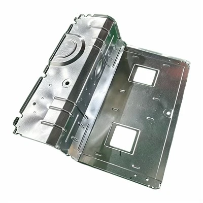
If you’re designing a new progressive die, or your current stripper plates are causing you headaches—whether that’s worn punches, scrap parts, downtime, or bad alignment—we can help. I’ve supplied stripper plates and full die components to shops ranging from small job shops to big auto parts manufacturers, and I’ve tweaked designs for hundreds of different stamping applications. Don’t waste another week troubleshooting a bad stripper plate. Hit us up to talk through your project, and we’ll help you design one that actually runs smooth, keeps scrap low, and gets your production line back on track.
Metal Stamping Dies References: 1. Tool and Manufacturing Engineers Handbook (TMEH), Volume 2: Forming, Society of Manufacturing Engineers, 2020. 2. Progressive Die Design Fundamentals, K. K. Jayesh, Industrial Press, 2018. 3. Die Design Handbook, E. P. DeGarmo, John Wiley & Sons, 2019. 4. High-Volume Stamping Component Design Guidelines, American Metal Stamping Association, 2021.
Dongguan Changdong Tool & Die Co., Ltd.
With abundant experience, we are one of the most reliable progressive dies manufacturers and suppliers in China. Please feel free to buy advanced progressive dies made in China here from our factory. Good service and quality products are available.
Address: No. 56-B, Fumin South Road, Dalang Town, Dongguan City, Guangdong Province, China
E-mail: sales@stamping-die.com
WebSite: https://www.metalstampingdie.com/
